PIC Project - CW Temp Circuit
I wanted a way to remotly check the temperature of a few things, in my case the repeater site at GB3PY. I decided on a system which used a radio to receive requests for the current temperature and send the results back to the user. Requests are by DTMF tones and the response is in CW, mores code.
The full design has not been tested, but I've managaed to do it with 2 sensors which works fine. This is an ongoing project and after a request from a friend about using PICAXE to decode DTMF I thought I would post details of the project which demonstrates the way I do it.
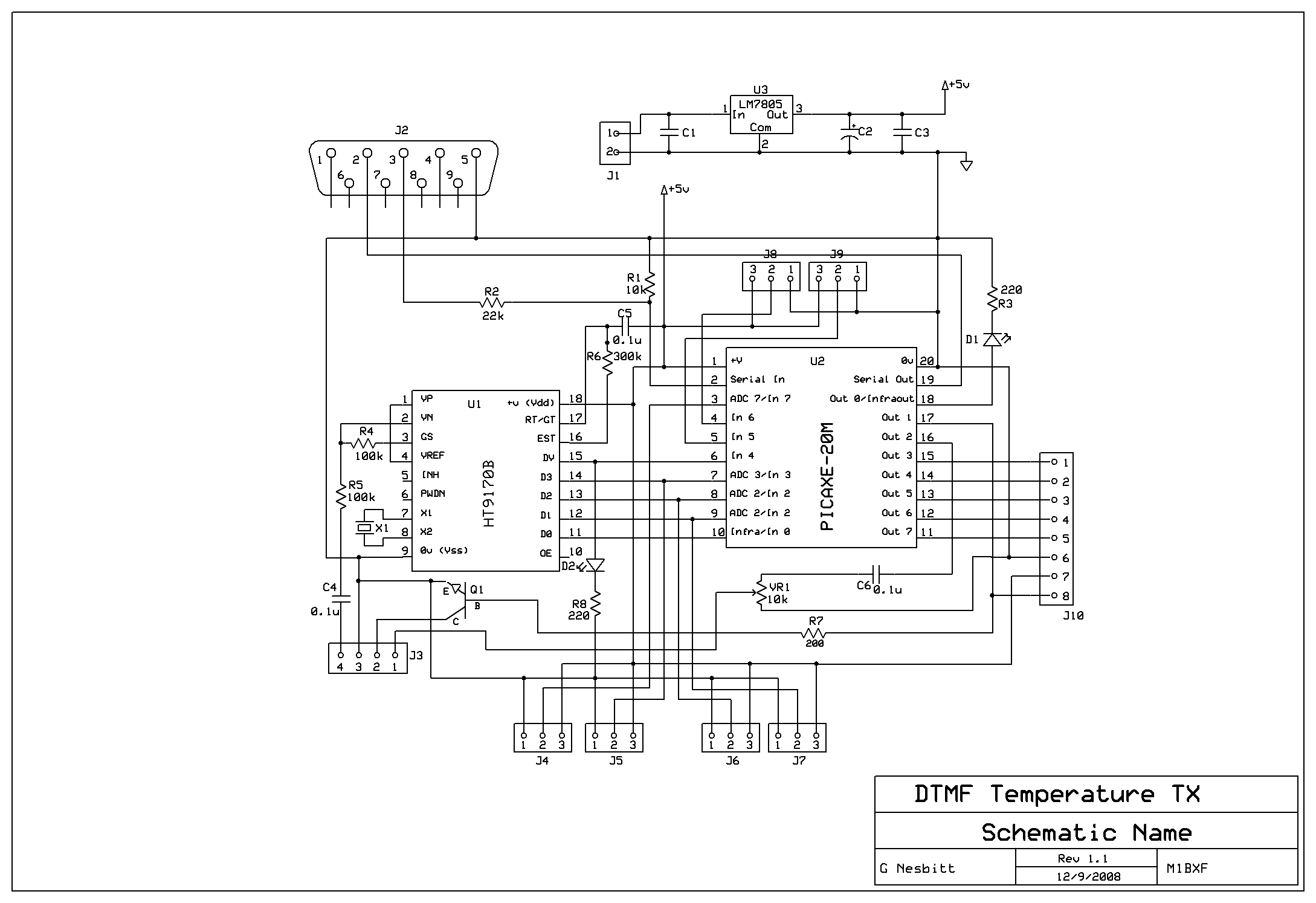
The PICAXE code, schematic and PCB layout are all available to download below. The code has a few things worth mentioning in it. When the HT9170B DTMF decoder chip gets a valid DTMF tone it outputs the value in binary (check the datasheet) but DTMF 1 outputs binary 1 or 0001 and DTMF 8 outputs binary 8 or 0100. Not only this there is a line called DV, pin 15 on the HT9170B which goes high when a valid DTMF tone is decode, this is great cause it is a way to tell the PICAXE it is time to read the input pins. You’ll see this in the code on line 41 ‘if pin4 = 0 then goto start’.
The code includes a PIN number, or a seqence of DTMF characters needed before the temerature is read, this could be removed, expanded or changed.
Basically I have a pin set in the code, this is between lines 42 and 72 and if the valid pin is entered then we read the temp and respond. The code below should be enough to read the DTMF value and store is register B0 using just the DTMF chip and PICAXE.
-----
START:
DEBUG ‘To see what B0 reads.
if pin4 = 0 then goto start 'Wait for the DTMF chip to signal an incoming tone on DV.
Read_DTMF: 'Routine to read the DTMF value.
B0 = pins
B0 = B0 - %00010000 ‘This line removes the DV signal from the value stored
‘so B0 is the actual value of the DTMF key pressed.
Goto START ‘Goto start, the value of B0 will be preserved.
-----
The full design has not been tested, but I've managaed to do it with 2 sensors which works fine. This is an ongoing project and after a request from a friend about using PICAXE to decode DTMF I thought I would post details of the project which demonstrates the way I do it.
The PICAXE code, schematic and PCB layout are all available to download below. The code has a few things worth mentioning in it. When the HT9170B DTMF decoder chip gets a valid DTMF tone it outputs the value in binary (check the datasheet) but DTMF 1 outputs binary 1 or 0001 and DTMF 8 outputs binary 8 or 0100. Not only this there is a line called DV, pin 15 on the HT9170B which goes high when a valid DTMF tone is decode, this is great cause it is a way to tell the PICAXE it is time to read the input pins. You’ll see this in the code on line 41 ‘if pin4 = 0 then goto start’.
The code includes a PIN number, or a seqence of DTMF characters needed before the temerature is read, this could be removed, expanded or changed.
Basically I have a pin set in the code, this is between lines 42 and 72 and if the valid pin is entered then we read the temp and respond. The code below should be enough to read the DTMF value and store is register B0 using just the DTMF chip and PICAXE.
-----
START:
DEBUG ‘To see what B0 reads.
if pin4 = 0 then goto start 'Wait for the DTMF chip to signal an incoming tone on DV.
Read_DTMF: 'Routine to read the DTMF value.
B0 = pins
B0 = B0 - %00010000 ‘This line removes the DV signal from the value stored
‘so B0 is the actual value of the DTMF key pressed.
Goto START ‘Goto start, the value of B0 will be preserved.
-----
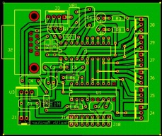
| ExpressPCB Schematic and PCB layout v1.0 (ZIP) |
| Schematic Layout v1.0 (BMP) |
| dtmf_cw_temp_module_v1.1.bas |
