PIC Based LVB Extender Project
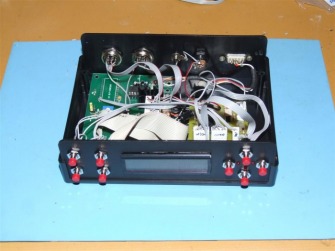
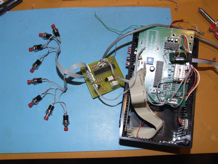
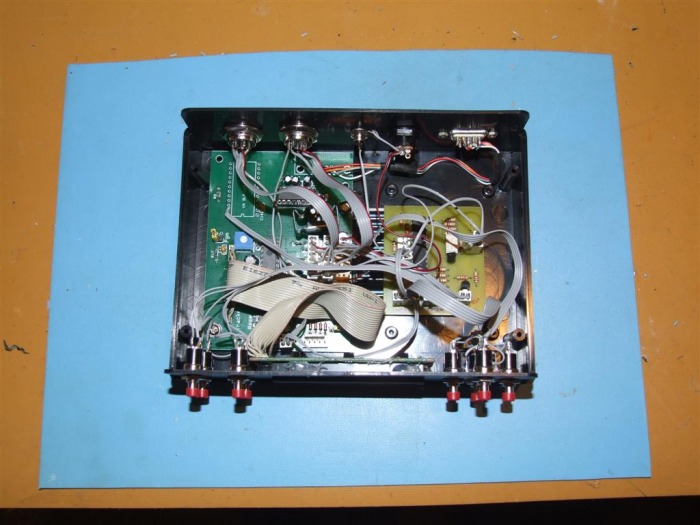
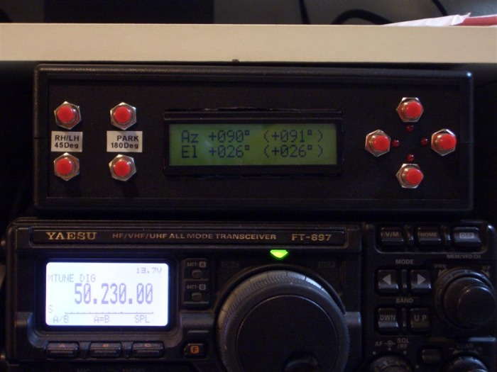
I've been using an LVB Tracker to control my directional antennas for sometime now - mainly for EME and satellite work. I've already built an elevation feedback circuit for this but I found I still lacked some of the fetures of more advanced rotators and with the LVB Tracker being controlled by serial using the GS-232 protocol I found this would be easy ro remidy using a PIC. Features I wanted to add were the ability to input a wanted heading and then leave the rotator to goto that heading instead of having to hold any button down as the rotator can be slow. I wanted to have a button for 'park' and an easy way to just rotate 45 degrees or 180 degrees (flip) at a time, I also added a button to switch the satellite antennas from RH to LH circular polarization and back again. Here is how I interfaced with the LVB Tracker...
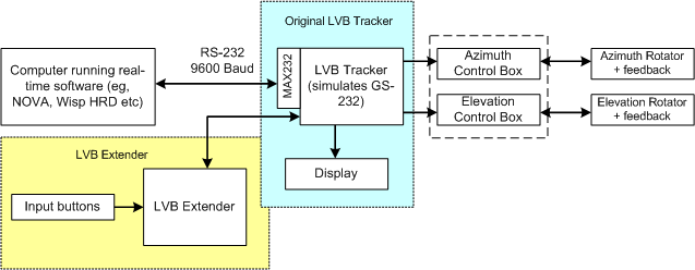
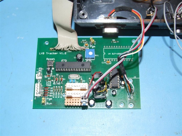
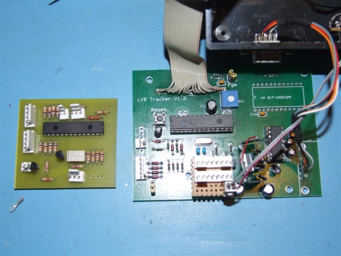
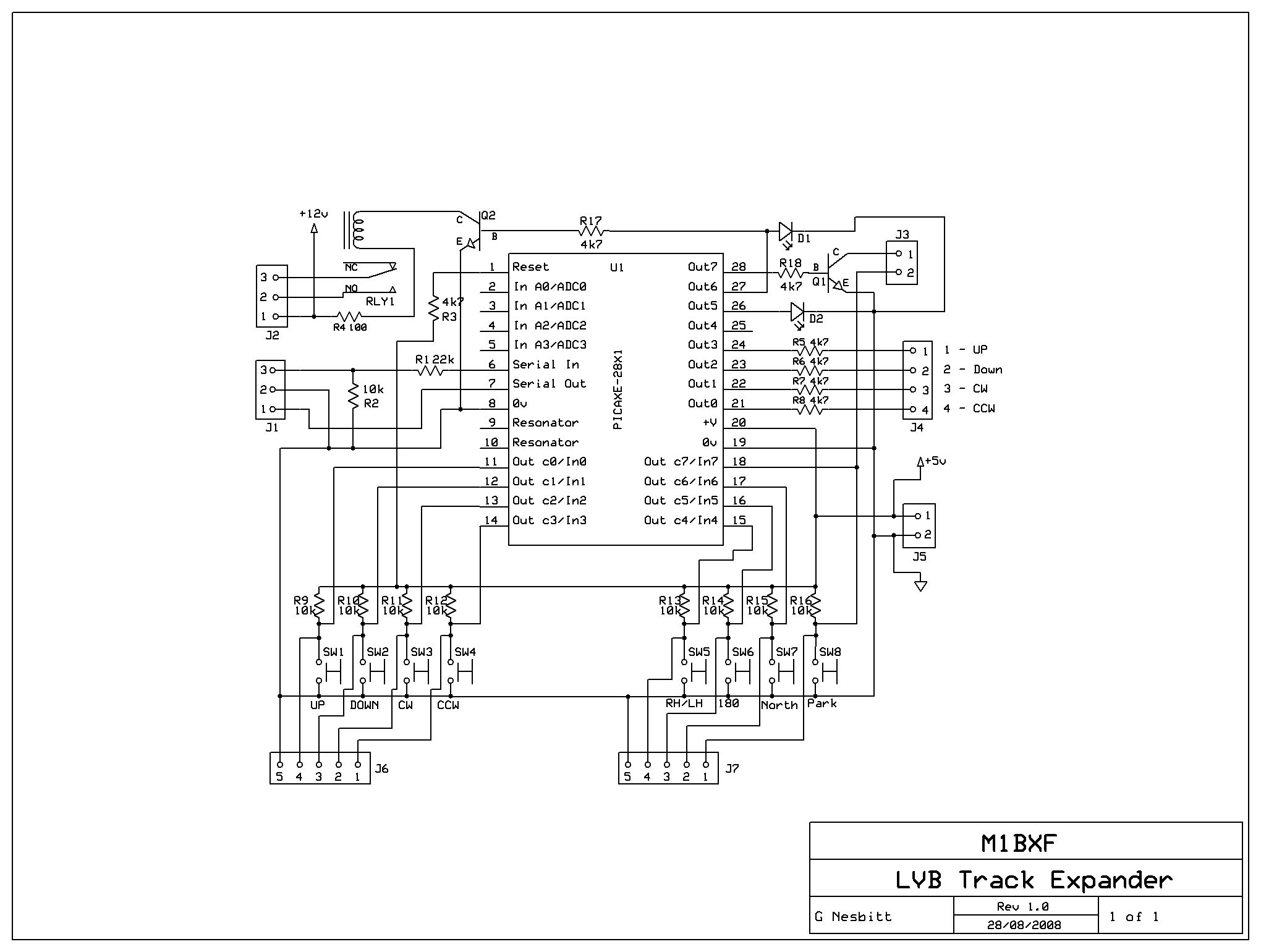
In the end I used a PICAXE-28X1 chip as I needed a bit of program memory and lots of input pins. The input buttons consist of UP, DOWN, CW & CCW plus LH/RH, Park, +45 degrees & +180 degrees. The serial from both PICs are TTL so I connected the serial to the LVB Tracker between the PIC and the MAX232 chip used for RS-232 level conversion. Whenever UP, DOWN, CW, CCW, +45 degrees or +180 degrees button are pressed the first thing the LVB Extender does is read the current positions using a "C2" command which prompt the LVB Tracker to output both current azimuth and elevation positions and from these positions the code works out what needs done with them. If it is UP, DOWN, CW or CCW then it runs a loop to increment or decrement the original position for the duration of the button being pressed with increasing speed over time. It writes the value back to the LVB Tracker on every loop. If the +45 degree or +180 degree buttons are pressed the LVB Extender again reads the current positions using a "C2" command and either adds 45 degrees or 180 degrees to the value and writes it back to the LVB Extender ensuring the write command has the originally read elevation value to this is not effected. The Park button sends the position to Park the antennas, from JO02ab for me this in 127 degrees azimuth and 0 degrees elevation (best for monitoring 144.300 into Europe). This is programmable in the code. The LH/RH button only toggles a relay to switch a voltage to the antennas. If azimuth value reaches 360 degrees the code converts it to 0 degrees and if it reaches 0 degrees it converts to 360, both are able to be set if you like to go over the limits a little. On elevation the counting is limited to between 0 and 90 degrees.

Downloads
| ExpressPCB Schematic and PCB layout v2.0 (ZIP) |
| Schematic Layout v2.0 (JPG) |
| PICAXE Code v3.0 (BAS) |
